Biology Learning Center CNS 213A, NO appointment needed:
- Mon 3-4 pm, Thurs 12:30-1:30pm
Other times by appointment

Biology Learning Center CNS 213A, NO appointment needed:
Other times by appointment
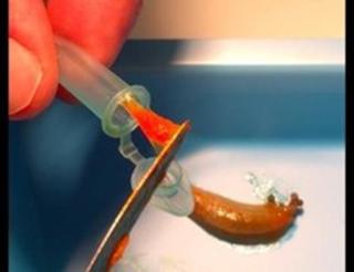
Credit: Rebecca Falconer, Ithaca College
We investigate the adhesive secretions produced by snails and slugs. We are currently focused on the sticky adhesive gels used as a defensive secretion by a few species of slugs. When threatened, these slugs secrete huge amounts of this adhesive from their back; it will spread rapidly over any surface it contacts and adhere strongly. This would provide a serious deterrent to any animal that tried to bite them!
One thing that makes these glues particularly exciting is that they are dilute gels, yet remarkably tough. Most gels are outstanding lubricants and you wouldn’t expect them to be useful adhesives, but these adhesive gels have many properties that make them well-suited for sticking to tissues; they adhere to wet, irregular surfaces, they set quickly, they can be remarkably tough, and they can bend and flex with the tissues rather than peeling or cracking. Thus, our goal is to determine how this glue gains these particular properties, so that we can guide the development of novel biomedical adhesives.
Publicity:
My contribution to the development of a novel medical glue was highlighted a few years ago by articles in the Smithsonian Magazine, Science News, PBS and The Washington Post. (See articles below.) Other involvement is included on my Research page.
More recently I was interviewed by:
Recently, two Ithaca College undergraduates, Chris Gallego and Becca Falconer, presented their work at the American Society for Biochemistry and Molecular Biology in Orlando, Florida and their work was highlighted by EurekAlert! and Science Daily.
Recent publications:
Andy Smith, Courtney Christoforo (2021), Beth Fleming (2021), Haley Haws (2020) and Matt Zeitler (2010). “Metal-binding proteins and cross-linking in the defensive glue of the slug Arion subfuscus”/ The Journal of the Royal Society Interface. This is the interdisciplinary journal of the Royal Society, focusing on work that bridges the physical sciences such as physics, math, chemistry and engineering with the life sciences (biological and medical sciences). https://royalsocietypublishing.org/doi/10.1098/rsif.2022.0611
Andy Smith, Phung Huynh (2022), Sarah Griffin (2020), Maria Baughn (2022) and Philip Monka (2017) published a paper in the journal Integrative and Comparative Biology. This paper identifies a novel adhesive protein from a biological glue. This protein binds strongly to a wide range of different surfaces. The paper identifies how the structure of the protein contributes to its versatility, and identifies the mechanisms by which it sticks to surfaces and interacts with the rest of the glue.